Stepper motor drivers are essential components in modern automation, robotics, and precision control systems. They act as the intermediary between a controller (such as a PLC or microcontroller) and a stepper motor, ensuring accurate movement by converting electrical pulses into mechanical motion. Whether you’re working with industrial machinery, 3D printers, or CNC systems, understanding how stepper motor drivers function, how to wire them, and how to integrate them with communication protocols like Modbus is crucial for optimal performance.
In this guide, we will explore four key aspects of stepper motor drivers:
PoStep60-256 – A closer look at this advanced stepper motor driver, its features, and applications.
How Does a Stepper Motor Driver Work? – Breaking down the principles of operation and control methods.
Stepper Motor Driver Wiring – A practical guide to connecting your driver correctly for reliable performance.
Stepper Motor Driver with Modbus – How to integrate stepper motor drivers into industrial networks using Modbus communication.
By the end of this article, you’ll have a solid understanding of stepper motor drivers, their configurations, and how to implement them in various applications. Let’s dive in!
What is the PoStep60-256 Stepper Motor Driver?
The PoStep60-256 represents a cutting-edge solution in stepper motor control, engineered for applications demanding precision, efficiency, and reliability. This advanced driver excels in environments ranging from industrial automation to high-resolution 3D printing, offering a blend of power and fine-tuned control that sets it apart from conventional stepper drivers.
At the heart of the PoStep60-256 lies its ability to deliver 256 microsteps per full step, a feature that drastically reduces motor vibration and ensures exceptionally smooth motion. This high microstepping resolution makes it particularly well-suited for tasks requiring ultra-fine positioning, such as CNC machining or delicate robotic movements.
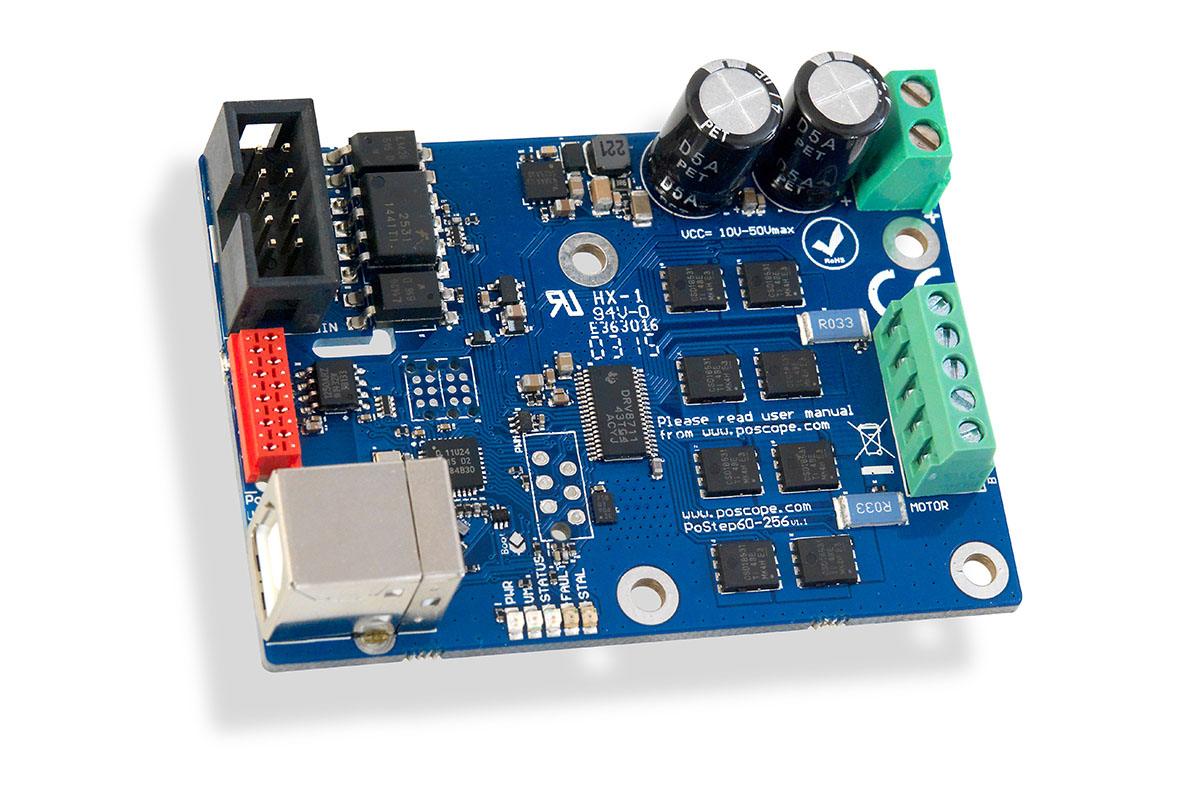
Designed for versatility, the PoStep60-256 accommodates a broad operational range, supporting input voltages from 12V to 60V DC and delivering up to 6A per phase. This flexibility allows it to power a wide spectrum of stepper motors, from compact NEMA 17 models to larger NEMA 23 or NEMA 34 variants.
Engineered with robustness in mind, the driver incorporates multiple protection mechanisms to safeguard both the motor and the control system. These include overcurrent detection, thermal shutdown to prevent overheating, and under-voltage lockout (UVLO), ensuring stable operation even in demanding conditions.
Control options are equally adaptable, with the PoStep60-256 accepting traditional step and direction signals for straightforward integration into CNC or 3D printing setups. Additionally, its Modbus communication capability enables seamless networking within industrial automation systems, allowing for centralized control and monitoring.
Compact yet powerful, the PoStep60-256 strikes an optimal balance between performance and practicality, making it a preferred choice for engineers and hobbyists alike who require precise, reliable stepper motor control.
How Does a Stepper Motor Driver Work?
At its core, a stepper motor driver acts as the crucial intermediary between a control system and a stepper motor, translating digital commands into precise mechanical movement. Unlike standard DC motors that rotate continuously when powered, stepper motors move in distinct increments, or “steps,” with each pulse from the driver advancing the motor by a fixed angle.
The Core Principles of Operation
Stepper motor drivers function by energizing the motor’s coils in a carefully controlled sequence. Inside a typical bipolar stepper motor, two electromagnetic coils interact with a toothed rotor. The driver alternates current flow between these coils in specific patterns, creating magnetic fields that pull the rotor into alignment. Each change in coil activation corresponds to one step of movement.
Microstepping, a key feature in advanced drivers like the PoStep60-256, further refines this process. Instead of simply switching full power between coils, the driver uses PWM (Pulse Width Modulation) to proportionally distribute current, allowing the motor to move in fractions of a full step. This results in smoother motion, reduced vibration, and higher positional accuracy—critical for applications like CNC machining or precision robotics.
Control Methods and Signal Processing
Most stepper drivers accept step and direction signals from a microcontroller, PLC, or dedicated motion controller. Each pulse on the “step” pin commands the motor to advance one increment, while the “direction” pin determines rotational orientation. Some drivers, including the PoStep60-256, also support Modbus communication, enabling integration into networked industrial systems for centralized control.
Current Regulation and Protection
To prevent overheating and ensure consistent torque, stepper drivers dynamically adjust coil current based on motor requirements. Techniques like chopper drive circuits monitor current flow and rapidly switch power to maintain optimal levels. Advanced models incorporate safeguards such as overcurrent shutdown, thermal protection, and voltage spike suppression, prolonging both motor and driver lifespan.
By precisely orchestrating power delivery and step sequencing, stepper motor drivers transform simple electrical pulses into controlled mechanical motion—making them indispensable in applications where precision, reliability, and programmability are paramount.
Stepper Motor Driver Wiring: A Practical Guide
Proper wiring is essential for ensuring reliable operation and optimal performance of your stepper motor system. Whether you’re setting up a PoStep60-256 or another stepper driver, understanding the correct connections will help prevent malfunctions, overheating, or damage to components.
Power Supply Connections
The stepper motor driver requires a stable DC power supply matching your motor’s voltage and current specifications. For the PoStep60-256, this typically means connecting a 12V–60V DC power source to the V+ and GND terminals. Always verify polarity—reversed connections can instantly damage the driver. A properly sized power supply with sufficient current capacity (e.g., at least 20% higher than the motor’s rated current) ensures smooth operation under load.
Motor Phase Wiring
Bipolar stepper motors have two coils (A+ / A− and B+ / B−), which must be correctly paired with the driver’s output terminals. Incorrect wiring can lead to weak torque, missed steps, or motor stuttering. Use a multimeter in continuity mode to identify coil pairs if motor documentation is unavailable. The PoStep60-256 clearly labels its A+, A−, B+, and B− terminals, simplifying this process.
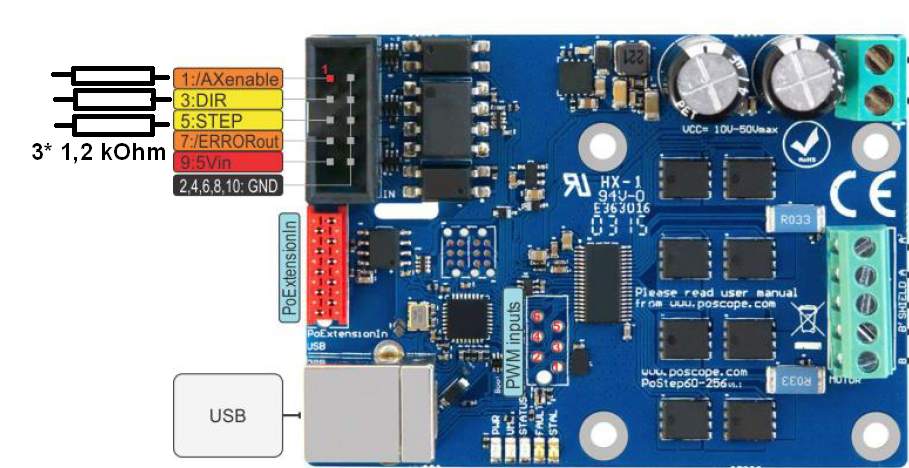
Control Signal Connections
Most drivers, including the PoStep60-256, accept step (pulse), direction, and enable signals from a controller like an Arduino or CNC board. These typically operate at 3.3V or 5V logic levels. For noise immunity in industrial environments:
- Use twisted-pair or shielded cables for signal wires.
- Keep high-power motor wires separate from control lines to avoid interference.
- Connect the controller’s ground to the driver’s GND to ensure a common reference.
Modbus Communication Wiring (Optional)
For PoStep60-256 units with Modbus support, connect the RS485 (A/B) terminals to your network using a twisted-pair cable with 120Ω termination resistors at each end. This minimizes signal reflections in long cable runs. Assign a unique Modbus address via DIP switches or software to avoid conflicts on the bus, becouse this optimizes stepper motor driver wiring.
Safety and Testing
Before powering on:
- Double-check all connections against the wiring diagram.
- Ensure no loose strands could cause shorts.
- Start with the motor unloaded and current limits set conservatively.
Correct wiring ensures your stepper motor system runs efficiently, with minimal noise and maximum longevity. The PoStep60-256’s clear terminal labeling and robust design simplify this process, but attention to detail remains critical for success.
Stepper Motor Driver with Modbus: Seamless Industrial Integration
Modern industrial automation demands more than just standalone motor control – it requires intelligent, interconnected systems. This is where Modbus-enabled stepper drivers like the PoStep60-256 shine, offering direct integration into industrial networks for centralized monitoring and control. Unlike traditional step/direction interfaces, Modbus communication transforms your stepper motor into a smart, addressable node in a larger automation ecosystem.
How Modbus Communication Enhances Stepper Control
The PoStep60-256 with Modbus support utilizes the widely-adopted RS485 physical layer running the Modbus RTU protocol. This implementation provides several key advantages:
Multi-axis Synchronization: Coordinate multiple steppers with precise timing by sending simultaneous commands through a single network cable, eliminating the need for complex parallel wiring.
Real-time Monitoring: Read actual motor current, position, and diagnostic data directly from the driver, enabling predictive maintenance and fault detection.
Remote Configuration: Adjust microstepping resolution, current limits, and acceleration profiles on-the-fly without physical access to the driver.
Scalable Architecture: Easily expand systems by adding more Modbus-compatible devices to the existing network with simple daisy-chained wiring.
Implementation Considerations
For optimal Modbus performance with your PoStep60-256:
- Network Topology: Use a linear bus structure with proper termination (120Ω resistors at each end)
- Addressing: Configure unique Modbus IDs for each driver via DIP switches or software
- Baud Rate: Match settings across all devices (typical 19200 or 38400 baud for industrial environments)
- Cable Selection: Shielded twisted-pair cables (AWG22 or thicker) for noise immunity in electrically noisy environments
Advanced Features Enabled by Modbus
The PoStep60-256 exposes numerous parameters through its Modbus interface:
- Position and speed registers for closed-loop control implementations
- Fault status registers for immediate error identification
- Current tuning parameters for adaptive torque control
- Motion profile buffers for complex movement sequences
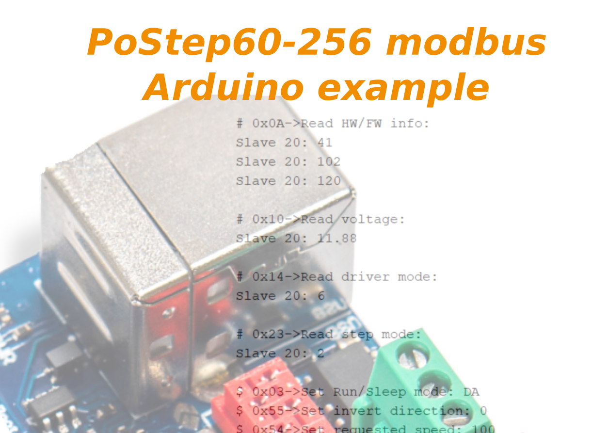
By leveraging these capabilities, engineers can implement sophisticated motion control strategies that would be impractical with conventional pulse/direction interfaces. The Modbus implementation in the PoStep60-256 follows standard function codes (03/04 for reading, 06/16 for writing), ensuring compatibility with virtually all industrial PLCs and SCADA systems.
Integrating a stepper motor driver with Modbus, particularly a feature-rich model like the PoStep60-256, elevates your motion control system from simple standalone operation to a fully networked industrial component. This approach future-proofs installations, reduces wiring complexity, and unlocks advanced monitoring and control capabilities essential for modern smart manufacturing environments.
Mastering Stepper Motor Drivers for Precision Motion Control
Stepper motor drivers serve as the critical link between digital control systems and mechanical motion, enabling precise positioning in applications ranging from 3D printing to industrial automation. Throughout this guide, we’ve explored the essential aspects of stepper motor driver technology, with a focus on the advanced PoStep60-256 and its capabilities.
Key Takeaways
The PoStep60-256 stands out as a high-performance driver, offering 256 microstepping, robust power handling (up to 60V/6A), and multiple control options, making it ideal for demanding applications.
Stepper motor drivers work by converting electrical pulses into precise mechanical steps, using techniques like microstepping and current regulation to ensure smooth, accurate motion.
Proper wiring is crucial for reliable operation—correct power supply connections, motor phase alignment, and signal isolation prevent issues like noise interference or motor stalling.
Modbus integration transforms stepper drivers into smart, networked devices, enabling centralized control, real-time monitoring, and multi-axis synchronization in industrial environments.
Choosing the Right Driver for Your Application
Whether you’re building a CNC machine, automating a production line, or developing a robotic system, selecting the appropriate stepper motor driver depends on several factors:
- Resolution requirements (microstepping capability)
- Power demands (voltage and current ratings)
- Control interface (step/direction vs. Modbus)
- Environmental conditions (thermal management, noise immunity)
The PoStep60-256 exemplifies how modern drivers combine precision, flexibility, and connectivity to meet diverse motion control needs. By understanding its operation, wiring, and communication capabilities, you can optimize performance in any application.
Final Thoughts
As automation continues to evolve, stepper motor drivers remain indispensable for precise motion control. With advancements like Modbus integration and high-resolution microstepping, drivers like the PoStep60-256 are pushing the boundaries of what’s possible in positioning accuracy and system integration.
By applying the knowledge from this guide, you’ll be well-equipped to design, configure, and troubleshoot stepper motor systems with confidence—ensuring reliable, high-performance operation in your projects.
Ready to take your motion control to the next level? The right stepper driver makes all the difference.
